Arduino/Genuino MKR1000
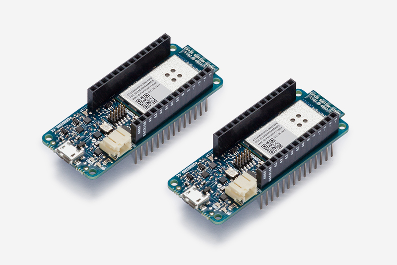
The Arduino/Genuino MKR1000 is based on the Atmel (Microchip Technology) ATSAMW25 SoC (System on Chip), that is part of the SmartConnect family of Microchip Wireless devices, specifically designed for IoT projects and devices.
The ATSAMW25 is composed of three main blocks:
- SAMD21 Cortex-M0+ 32bit low power ARM MCU
- WINC1500 low power 2.4GHz IEEE® 802.11 b/g/n Wi-Fi
- ECC508 CryptoAuthentication
The ATSAMW25 includes also a single 1x1 stream PCB Antenna.
The design includes a Li-Po charging circuit that allows the Arduino/Genuino MKR1000 to run on battery power or external 5V, charging the Li-Po battery while running on external power. Switching from one source to the other is done automatically.
All these features make this device the preferred choice for the emerging IoT battery-powered projects in a compact form factor.
The USB port can be used to supply power (5V) to the device. The Arduino/Genuino MKR1000 is able to run with or without the Li-Po battery connected and has limited power consumption.
Warning
Unlike most Arduino & Genuino devices, the MKR1000 runs at 3.3V. The maximum voltage that the I/O pins can tolerate is 3.3V. Applying voltages higher than 3.3V to any I/O pin could damage the device.
Note
All the reported information are extracted from the official Arduino/Genuino MKR1000 page, visit this page for more details and updates.
Pin Mapping
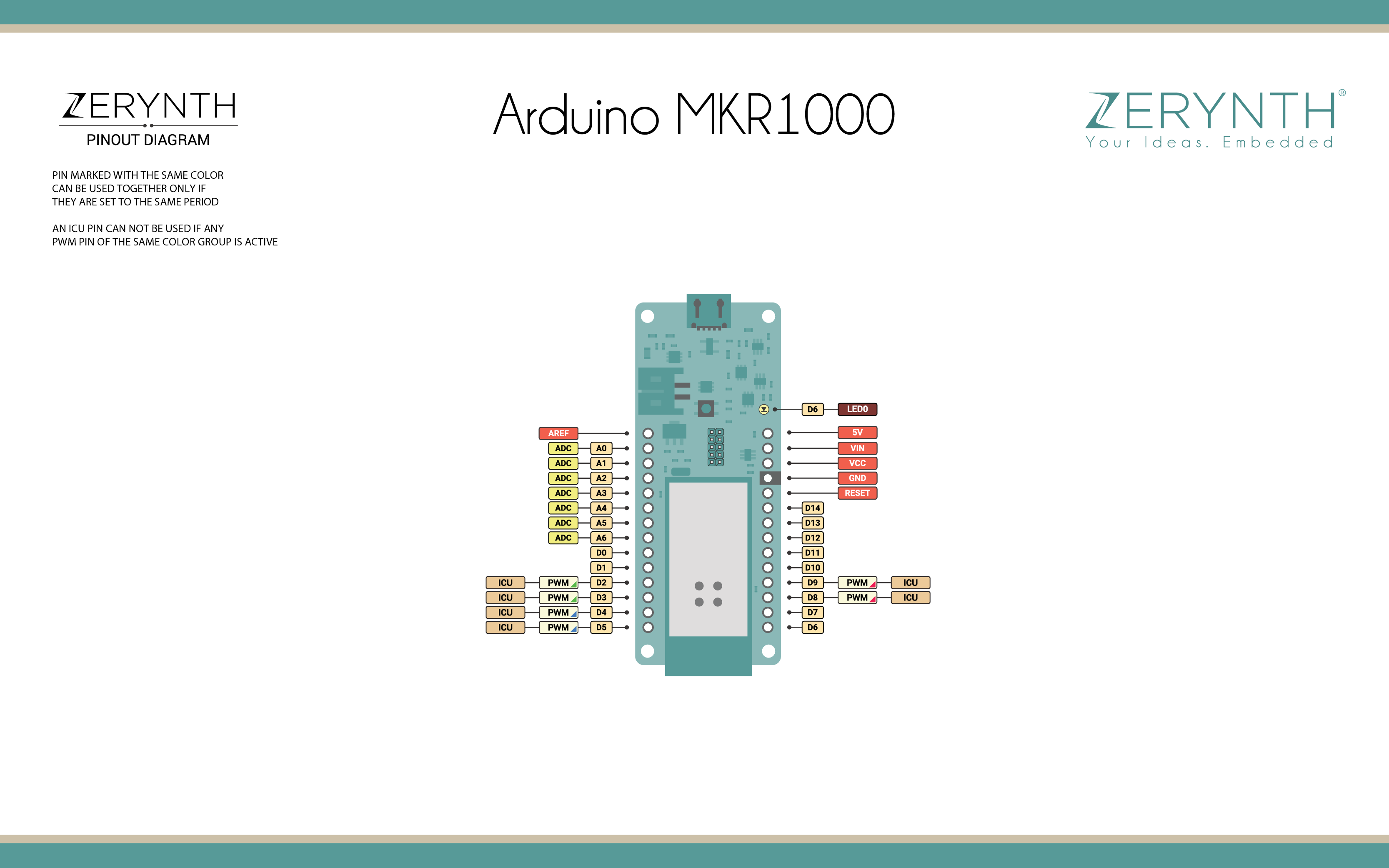
Arduino/Genuino MKR1000 Official Schematic, Reference Design and Pin Mapping are available on the official Arduino/Genuino MKR1000 reference page.
Flash Layout
The internal flash of the Arduino/Genuino MKR1000 is organized as a single bank of 256k.
Note
Zerynth VM preserves SAM-BA Bootloader located at Flash start.
Device Summary
- Microcontroller: SAMD21 Cortex-M0+ 32bit low power ARM MCU
- Power Supply (USB/VIN): 5V
- Supported Battery: Li-Po single cell, 3.7V, 700mAh minimum
- Operating Voltage: 3.3V
- Digital I/O Pins (DIO): 14
- Analog Input Pins (ADC): 7
- UARTs: 1
- SPIs: 1
- I2Cs: 1
- Flash Memory: 256 KB
- SRAM: 32 KB
- Clock Speed: 48 MHz
- Size (LxW mm): 61.5 x 25.0
Power
Battery capacity: Li-Po batteries are charged up to 4.2V with a current that is usually half of the nominal capacity. For Arduino/Genuino MKR1000 a specialized chip that has a preset charging current of 350mAh is used. This means that the MINIMUM capacity of the Li-Po battery should be 700 mAh. Smaller cells will be damaged by this current and may overheat, develop internal gasses and explode, setting on fire the surroundings. It is strongly recommended to select a Li-Po battery of at least 700mAh capacity. A bigger cell will take more time to charge, but won’t be harmed or overheated. The chip is programmed with 4 hours of charging time, then it goes into automatic sleep mode. This will limit the amount of charge to max 1400 mAh per charging round.
Battery connector: If you want to connect a battery to your MKR1000 be sure to search one with female 2 pin JST PHR2 Type connector. Polarity: looking at the device connector pins, polarity is Left = Positive, Right = GND. Download here the Connector datasheet. On the MKR1000, connector is a Male 2pin JST PH Type.
Vin: This pin can be used to power the device with a regulated 5V source. If the power is fed through this pin, the USB power source is disconnected. This is the only way you can supply 5v (range is 5V to maximum 6V) to the device not using USB. This pin is an INPUT.
5V: This pin outputs 5V from the the device when powered from the USB connector or from the VIN pin of the device. It is unregulated and the voltage is taken directly from the inputs. As an OUTPUT, it should not be used as an input pin to power the device.
VCC: This pin outputs 3.3V through the on-board voltage regulator. This voltage is the same regardless the power source used (USB, Vin and Battery).
LED ON: This LED is connected to the 5V input from either USB or VIN. It is not connected to the battery power. This means that it lits up when power is from USB or VIN, but stays off when the device is running on battery power. This maximizes the usage of the energy stored in the battery. It is therefore normal to have the device properly running on battery power without the LED ON being lit.
CHARGE LED: The CHARGE LED on the device is driven by the charger chip that monitors the current drawn by the Li-Po battery while charging. Usually it will lit up when the device gets 5V from VIN or USB and the chip starts charging the Li-Po battery connected to the JST connector. There are several occasions where this LED will start to blink at a frequency of about 2Hz. This flashing is caused by the following conditions maintained for a long time (from 20 to 70 minutes):
- No battery is connected to JST connector.
- Overdischarged/damaged battery is connected. It can’t be recharged.
- A fully charged battery is put through another unnecessary charging cycle. This is done disconnecting and reconnecting either VIN or the battery itself while VIN is connected.
Note
All the reported information are extracted from the official Arduino/Genuino MKR1000 page, visit this page for more details and updates.
Connect, Register, Virtualize and Program
To recognize the device, Windows machines require drivers that can be downloaded from the Arduino/Genuino MKR1000 guide, otherwise this can be done by using the Zadig utility version 2.2 or greater; OSX and Linux machines will recognize the device automatically.
Note
Drivers must be installed for both Standard and Virtualization Mode of the MKR1000 device.
Warning
Remember, when using the Zadig utility, to select “Options > List all devices” to search for the MKR1000 device. Select the Usb CDC driver for the standard mode and any other for the virtualization mode.
Once connected on a USB port, if drivers have been correctly installed, the Arduino/Genuino MKR1000 device is recognized by the Zerynth Studio and listed in the Device Management Toolbar.
Follow these steps to register and virtualize a Arduino/Genuino MKR1000:
- Put the MKR1000 in Virtualization Mode:
- Double click on the RST button;
- Select the MKR1000 Virtualizable on the Device Management Toolbar;
- Register the device by clicking the “Z” button from the Zerynth Studio;
- Create a Virtual Machine for the device by clicking the “Z” button for the second time;
- Virtualize the device by clicking the “Z” button for the third time.
Note
During these operations the MKR1000 device must be in Virtualization Mode. if the device returns in standard mode, it is necessary to put it in DFU Mode again.
Zerynth scripts can be uploaded on virtualized Arduino/Genuino MKR1000 by clicking the dedicated upload button available on the Current Project panel of the IDE. Follow these steps to upload a Zerynth script on a virtualized Arduino/Genuino MKR1000:
After virtualization, the Arduino/Genuino MKR1000 is ready to be programmed and the Zerynth scripts uploaded. Just Select the virtualized device from the “Device Management Toolbar”, click the dedicated “upload” button of Zerynth Studio and reset the device by pressing the RST on-board button when asked.
Important
To exploit the Wi-Fi chip functionalities of the Arduino/Genuino MKR1000, the lib.microchip.winc1500 library must be installed and imported in the Zerynth script.
Firmware Over the Air update (FOTA)
The Firmware Over the Air feature allows to update the device firmware at runtime. Zerynth FOTA in the Arduino/Genuino MKR1000 device is available for bytecode only.
Flash Layout is shown in table below:
| Start address | Size | Content |
|---|---|---|
| 0x00002000 | 94Kb | VM Slot |
| 0x00019600 | 77Kb | Bytecode Slot 0 |
| 0x0002CB00 | 77Kb | Bytecode Slot 1 |
Power Management and Secure Firmware
Power Management feature allows to optimize power consumption by putting the device in low consumption state.
Secure Firmware feature allows to detect and recover from malfunctions and, when supported, to protect the running firmware (e.g. disabling the external access to flash or assigning protected RAM memory to critical parts of the system).
Both these features are strongly platform dependent; more information at Power Management - Microchip SAMD21 section and Secure Firmware - Microchip SAMD21 section.