ESP32 Pico v4
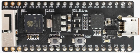
The ESP32 Pico v4 is a mini development board produced by Espressif. The core of this board is the ESP32-PICO-D4, based on ESP32 microcontroller, a System-in-Package (SIP) module with complete Wi-Fi and Bluetooth functionalities.
Comparing to other ESP32 chips, the ESP32-PICO-D4 integrates several peripheral components in one single package, that otherwise would need to be installed separately. This includes a 40 MHz crystal oscillator, 4 MB flash, filter capacitors and RF matching links in.
Pin Mapping
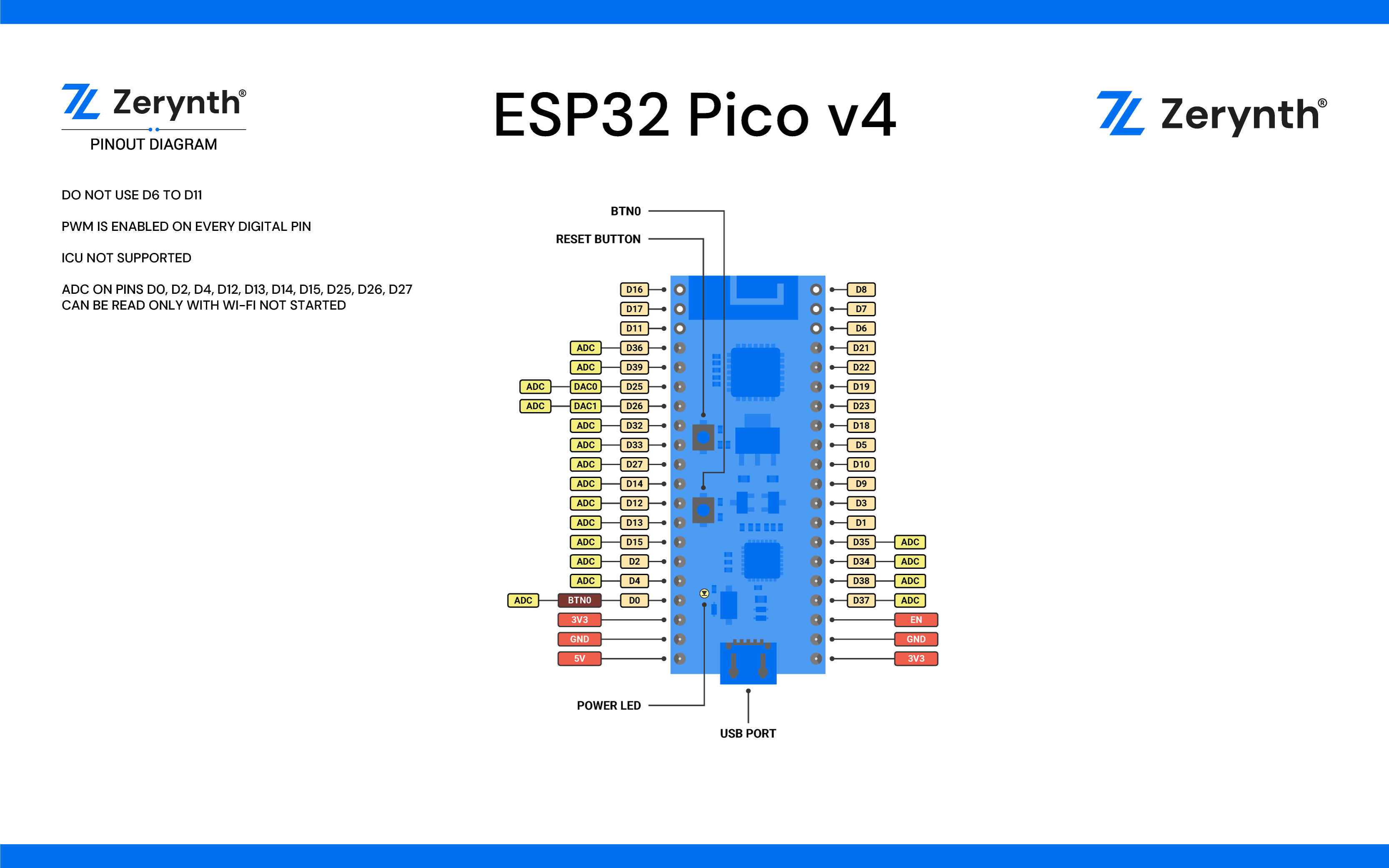
Official reference for ESP32 Pico v4 can be found here.
Flash Layout
The internal flash of the ESP32 module is organized in a single flash area with pages of 4096 bytes each. The flash starts at address 0x00000, but many areas are reserved for Esp32 IDF SDK and Zerynth VM. There exist two different layouts based on the presence of BLE support.
In particular, for non-BLE VMs:
| Start address | Size | Content |
|---|---|---|
| 0x00009000 | 16Kb | Esp32 NVS area |
| 0x0000D000 | 8Kb | Esp32 OTA data |
| 0x0000F000 | 4Kb | Esp32 PHY data |
| 0x00010000 | 1Mb | Zerynth VM |
| 0x00110000 | 1Mb | Zerynth VM (FOTA) |
| 0x00210000 | 512Kb | Zerynth Bytecode |
| 0x00290000 | 512Kb | Zerynth Bytecode (FOTA) |
| 0x00310000 | 512Kb | Free for user storage |
| 0x00390000 | 448Kb | Reserved |
For BLE VMs:
| Start address | Size | Content |
|---|---|---|
| 0x00009000 | 16Kb | Esp32 NVS area |
| 0x0000D000 | 8Kb | Esp32 OTA data |
| 0x0000F000 | 4Kb | Esp32 PHY data |
| 0x00010000 | 1216Kb | Zerynth VM |
| 0x00140000 | 1216Kb | Zerynth VM (FOTA) |
| 0x00270000 | 320Kb | Zerynth Bytecode |
| 0x002C0000 | 320Kb | Zerynth Bytecode (FOTA) |
| 0x00310000 | 512Kb | Free for user storage |
| 0x00390000 | 448Kb | Reserved |
Device Summary
- Microcontroller: Tensilica 32-bit Single-/Dual-core CPU Xtensa LX6
- Operating Voltage: 3.3V
- Input Voltage: 7-12V
- Digital I/O Pins (DIO): 28
- Analog Input Pins (ADC): 8
- Analog Outputs Pins (DAC): 2
- UARTs: 3
- SPIs: 2
- I2Cs: 3
- Flash Memory: 4 MB
- SRAM: 520 KB
- Clock Speed: 240 Mhz
- Wi-Fi: IEEE 802.11 b/g/n/e/i:
- Integrated TR switch, balun, LNA, power amplifier and matching network
- WEP or WPA/WPA2 authentication, or open networks
Power
Power to the Esp32 Pico v4 is supplied via the on-board USB Micro B connector or directly via the “VIN” pin. The power source is selected automatically.
The device can operate on an external supply of 6 to 20 volts. If using more than 12V, the voltage regulator may overheat and damage the device. The recommended range is 7 to 12 volts.
Connect, Register, Virtualize and Program
The Esp32 Pico v4 comes with a serial-to-usb chip on board that allows programming and opening the UART of the ESP32 module. Drivers may be needed depending on your system (Mac or Windows) and can be download from the official Espressif documentation page. In Linux systems, the Pico v4 should work out of the box.
Note
For Linux Platform: to allow the access to serial ports the user needs read/write access to the serial device file. Adding the user to the group, that owns this file, gives the required read/write access: Ubuntu distribution –> dialout group; Arch Linux distribution –> uucp group.
Once connected on a USB port, if drivers have been correctly installed, the Pico v4 device is recognized by Zerynth Studio. The next steps are:
- Select the Pico v4 on the Device Management Toolbar (disambiguate if necessary);
- Register the device by clicking the “Z” button from the Zerynth Studio;
- Create a Virtual Machine for the device by clicking the “Z” button for the second time;
- Virtualize the device by clicking the “Z” button for the third time.
Note
No user intervention on the device is required for registration and virtualization process.
After virtualization, the Pico v4 is ready to be programmed and the Zerynth scripts uploaded. Just Select the virtualized device from the “Device Management Toolbar” and click the dedicated “upload” button of Zerynth Studio.
Note
No user intervention on the device is required for the uplink process.
Firmware Over the Air update (FOTA)
The Firmware Over the Air feature allows to update the device firmware at runtime. Zerynth FOTA in the DevKitC device is available for bytecode and VM.
Flash Layout is shown in table below:
| Start address | Size | Content |
|---|---|---|
| 0x00010000 | 1Mb | Zerynth VM (slot 0) |
| 0x00110000 | 1Mb | Zerynth VM (slot 1) |
| 0x00210000 | 512Kb | Zerynth Bytecode (slot 0) |
| 0x00290000 | 512Kb | Zerynth Bytecode (slot 1) |
For BLE VMs:
| Start address | Size | Content |
|---|---|---|
| 0x00010000 | 1216Kb | Zerynth VM (slot 0) |
| 0x00140000 | 1216Kb | Zerynth VM (slot 1) |
| 0x00270000 | 320Kb | Zerynth Bytecode (slot 0) |
| 0x002C0000 | 320Kb | Zerynth Bytecode (slot 1) |
For Esp32 based devices, the FOTA process is implemented mostly by using the provided system calls in the IDF framework. The selection of the next VM to be run is therefore a duty of the Espressif bootloader; the bootloader however, does not provide a failsafe mechanism to revert to the previous VM in case the currently selected one fails to start. At the moment this lack of a safety feature can not be circumvented, unless by changing the bootloader. As soon as Espressif relases a new IDF with such feature, we will release updated VMs.
Secure Firmware
Secure Firmware feature allows to detect and recover from malfunctions and, when supported, to protect the running firmware (e.g. disabling the external access to flash or assigning protected RAM memory to critical parts of the system).
This feature is strongly platform dependent; more information at Secure Firmware - ESP32 section.
Zerynth Secure Socket
To be able to use Zerynth Secure Socket on esp32 boards NATIVE_MBEDTLS: true must be used instead of ZERYNTH_SSL: true in the project.yml file.
Missing features
Not all IDF features have been included in the Esp32 based VMs. In particular the following are missing but will be added in the near future:
- Touch detection support