Polaris 2G
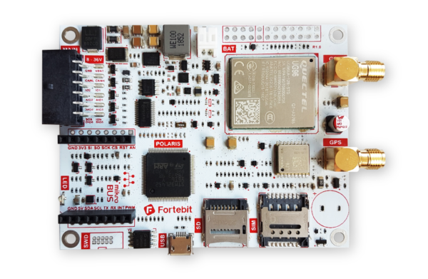
Polaris 2G provided by Fortebit is a professional GPS/GLONASS vehicle tracker and IoT development platform.
The Polaris 2G hardware includes a powerful 32-bit ARM Cortex-M4 controller with low-power features (STM32L452), a GSM/GPRS modem for wireless connectivity, a GPS/GLONASS receiver with Assisted-GPS,on-board accelerometer and SD card socket, mikroBus™ expansion slot, plenty of I/O, and a wide operating temperature range of -35°C to +80°C.
With Polaris 2G, many IoT applications can be developed related to real-time asset tracking, geo-fencing, sensors logging, battery monitoring, remote controlling, and others. It works right out of the box as vehicle tracker; the only requirement is a SIM card.
Important
Polaris 2G belongs to Polaris family of board by Fortebit. The lib.fortebit.polaris library is available and can be imported to abstract your Zerynth project from a specific Polaris board.
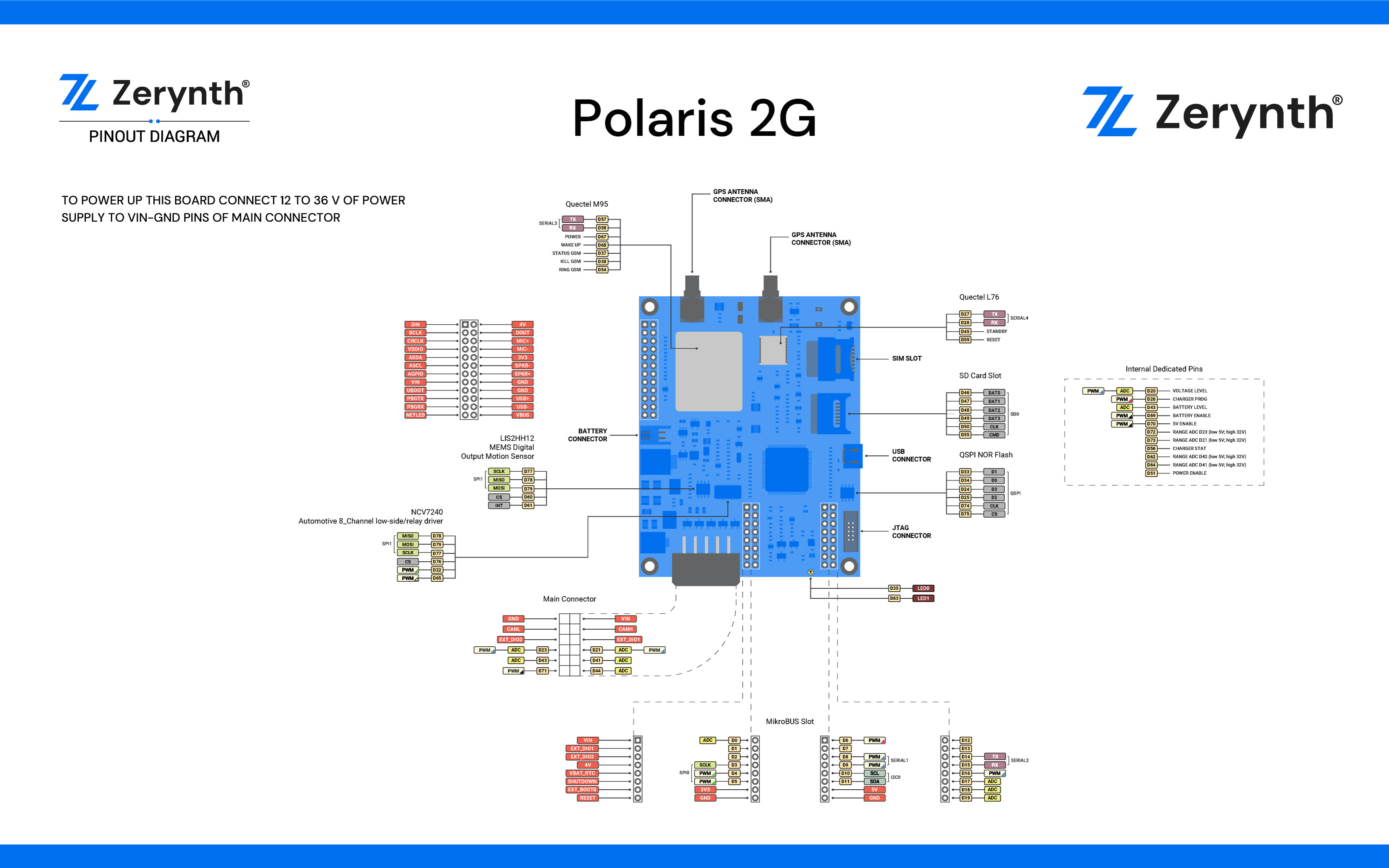
Pin Mapping
Flash Layout
The internal flash of the Polaris 2G is organized in one block divided in 256 pages of 2Kb each. The flash memory address starts at 0x8000000 and can be read and written from a Zerynth program using the internal flash module.
Warning
If internal flash is used in a Zerynth program, it is suggested to begin using pages from the end of flash towards the virtual machine, to minimize the chance of clashes.
Since writing to a sector entails erasing it first, the write operation can be slow even for small chunks of data, depending on the size of the choosen sector.
Device Summary
- Microcontroller: STM32L452 ARM®32-bit Cortex®-M4 CPU
- Operating Voltage: 3.3V
- Input Voltage: 8-36V
- Digital I/O Pins (DIO): 69
- Analog Input Pins (ADC): 11
- UARTs: 4
- USB: 1
- SPIs: 2
- I2Cs: 1
- SD Card Slot: 1
- SIM Card Slot: 1
- MikroBus Click Slot: 1
- Flash Memory: 512 KB
- SRAM: 160 KB
- Clock Speed: 80 MHz
Power
On the Polaris 2G the power supply is provided by an external Source: VIN (8V-36V) or through the JST connector for a 3.7/4.2 V backup battery. The power source is selected automatically and when both power supply are provided, the main source can be used to enable charging the backup battery.
Note
Polaris 2G can be programmed through USB connector or through ST-Link debugger connected to the related JTAG connector.
Warning
When the device is connected to the PC by USB or by ST-LINK debugger, VUSB and Vcc are not connected as Power supply. External Power Supply or Battery Power Supply must be always provided.
Connect, Register, Virtualize and Program
On Windows machines two set of drivers may be installed: the DFU drivers and the USB serial drivers. This can be done by using the Zadig utility version 2.2 or greater. Use the Zadig utility once with the Polaris 2G in DFU mode (see below) and once after the device has been virtualized.
Note
Remember to select “Options > List all devices” to search for the Polaris 2G device.
- In DFU mode, the VID:PID you should see is 0483:5740 and the Polaris 2G si recognized as “STM32 BOOTLOADER”.
- For the virtualized Polaris 2G (DFU MODE) the VID:PID is 0483:DF12.
Warning
In DFU mode any driver is ok, except Usb CDC; for the virtualized Polaris the only valid driver is Usb CDC.
Note
It could be necessary to temporarily disable the digitally signed driver enforcement policy of Windows to allow the driver installation. There are good instructions on how to do that in this guide.
On MAC OSX and Linux USB drivers are not required.
Note
For Linux Platform: to allow the access to serial ports the user needs read/write access to the serial device file. Adding the user to the group, that owns this file, gives the required read/write access: Ubuntu distribution –> dialout group; Arch Linux distribution –> uucp group.
If the device is still not recognized or not working, the following udev rules may need to be added:
#Polaris 2G Device
SUBSYSTEMS=="usb", ATTRS{idVendor}=="0483", ATTRS{idProduct}=="5740", MODE="0666", GROUP="users", ENV{ID_MM_DEVICE_IGNORE}="1"
SUBSYSTEMS=="tty", ATTRS{idVendor}=="0483", ATTRS{idProduct}=="df12", MODE="0666", GROUP="users", ENV{ID_MM_DEVICE_IGNORE}="1"
Once connected to a USB port the Polaris device can be seen as a Virtual Serial port or as a DFU device depending on its virtualized/virtualizable status and it is automatically recognized by Zerynth Studio. The next steps are:
- Put the Polaris in DFU Mode (Device Firmware Upgrade):
- Click on “Device Info” button;
- Wait until “Device Management Toolbar” blinks yellow;
- Select the Polaris on the Device Management Toolbar (Disambiguate if necessary);
- Register the device by clicking the “Z” button from the Zerynth Studio;
- Create a Virtual Machine for the device by clicking the “Z” button for the second time;
- Virtualize the device by clicking the “Z” button for the third time.
Note
During these operations the Polaris 2G device must be in DFU mode. if the device returns in standard mode, it is necessary to put it in DFU Mode again.
After virtualization, the Polaris 2G is ready to be programmed and the Zerynth scripts uploaded. Just Select the virtualized device from the “Device Management Toolbar” and click the dedicated “upload” button of Zerynth Studio.
Power Management and Secure Firmware
Power Management feature allows to optimize power consumption by putting the device in low consumption state.
Secure Firmware feature allows to detect and recover from malfunctions and, when supported, to protect the running firmware (e.g. disabling the external access to flash or assigning protected RAM memory to critical parts of the system).
Both these features are strongly platform dependent; more information at Power Management - STM32F section and Secure Firmware - STM32F section.