Sony Spresense
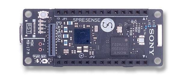
Spresense is a compact development board based on Sony’s power-efficient multicore microcontroller CXD5602.
- Integrated GPS - The embedded GNSS with support for GPS, QZSS and GLONASS enables applications where tracking is required.
- Multicore microcontroller - Spresense is powered by Sony’s CXD5602 microcontroller (ARM® Cortex®-M4F × 6 cores), with a clock speed of 156 MHz.
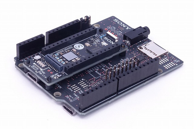
The Spresense consists of two boards:
Pin Mapping
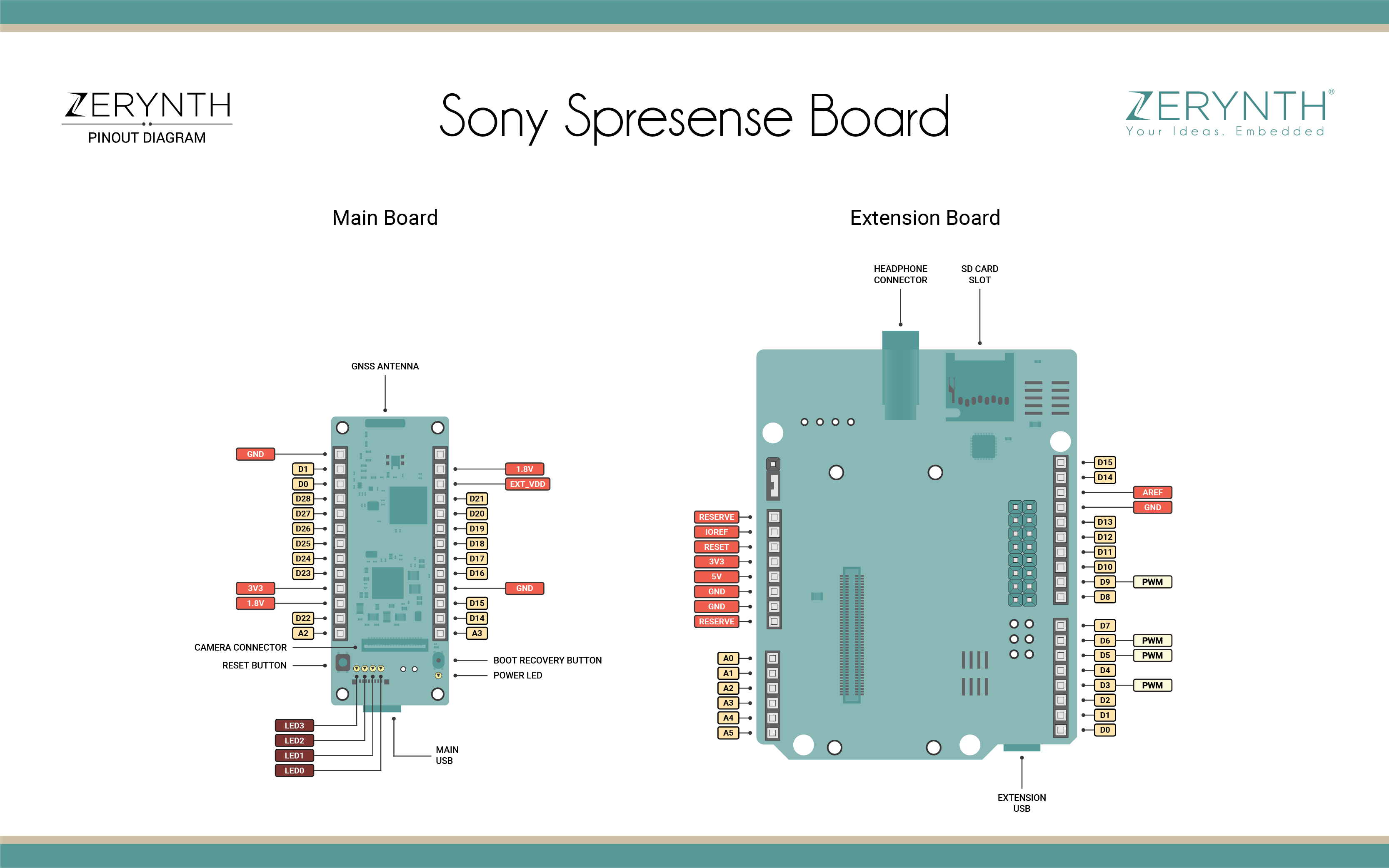
Official reference for Sony Spresense can be found here.
Device Summary
- Sony’s CXD5602 Processor (ARM Cortex-M4F)
- 8 MB Flash memory
- PCB with small footprint
- Dedicated camera connector
- GNSS (GPS) antenna
- Pins and LEDs
- Multiple GPIO (UART, SPI, I2C, I2S)
- 2 ADC channels
- Application LED x 4 (Green)
- Power LED (Blue)
- USB serial port
Power
The maximum current that can be drained from the Spresense main board micro USB connector is 500mA. This is true also when both the main board and extension board are mounted and have separate USB power connected.
In case that the 500mA current from the micro USB connector is not sufficient it is possible to supply more power using the battery terminal CN1 on the main board. The CN1 battery connector’s recommended operating voltage is 3.6 to 4.4V with an absolute maximum voltage of 7V.
It is necessary to solder on the main board to mount a battery connector on CN1.
More here on the official documentation.
Connect, Register, Virtualize and Program
The Sony Spresense Main Board comes with a USB to UART bridge on board that allows programming and opening the serial monitor when the board is plugged. Drivers may be needed depending on your system (Mac or Windows) and can be download from the official Sony documentation page. In Linux systems, the Spresense should work out of the box.
Note
For Linux Platform: to allow the access to serial ports the user needs read/write access to the serial device file. Adding the user to the group, that owns this file, gives the required read/write access: Ubuntu distribution –> dialout group; Arch Linux distribution –> uucp group.
Once connected through the Main USB port, if drivers have been correctly installed, the Spresense device is recognized by Zerynth Studio. The next steps are:
- Select the Spresense on the Device Management Toolbar (disambiguate if necessary);
- Burn the Spresense Bootloader clicking the “Info” button, then “Burn Bootloader”;
- Register the device by clicking the “Z” button from the Zerynth Studio;
- Create a Virtual Machine for the device by clicking the “Z” button for the second time;
- Virtualize the device by clicking the “Z” button for the third time.
Note
No user intervention on the device is required for registration and virtualization process.
After virtualization, the Spresense is ready to be programmed and the Zerynth scripts uploaded. Just Select the virtualized device from the “Device Management Toolbar” and click the dedicated “upload” button of Zerynth Studio.
Note
No user intervention on the device is required for the uplink process.
Extra notes
As reported in the previous section, Spresense Bootloader needs to be burnt on Spresense boards as a preliminary operation.
SPI modes: when the pin D10 is chosen as Chip Select pin, SPI modes follow the Motorola SPI Frame Format. If an independent CS control is desired, please choose a different CS pin.