Infineon XMC4200 Digital Power Control Card
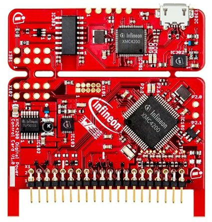
Infineon XMC4200 Digital Power Control Card is equipped with the ARM Cortex-M4 based XMC4200 microcontroller (MCU) from Infineon Technologies.
Official reference for Infineon XMC4200 Digital Power Control Card can be found here.
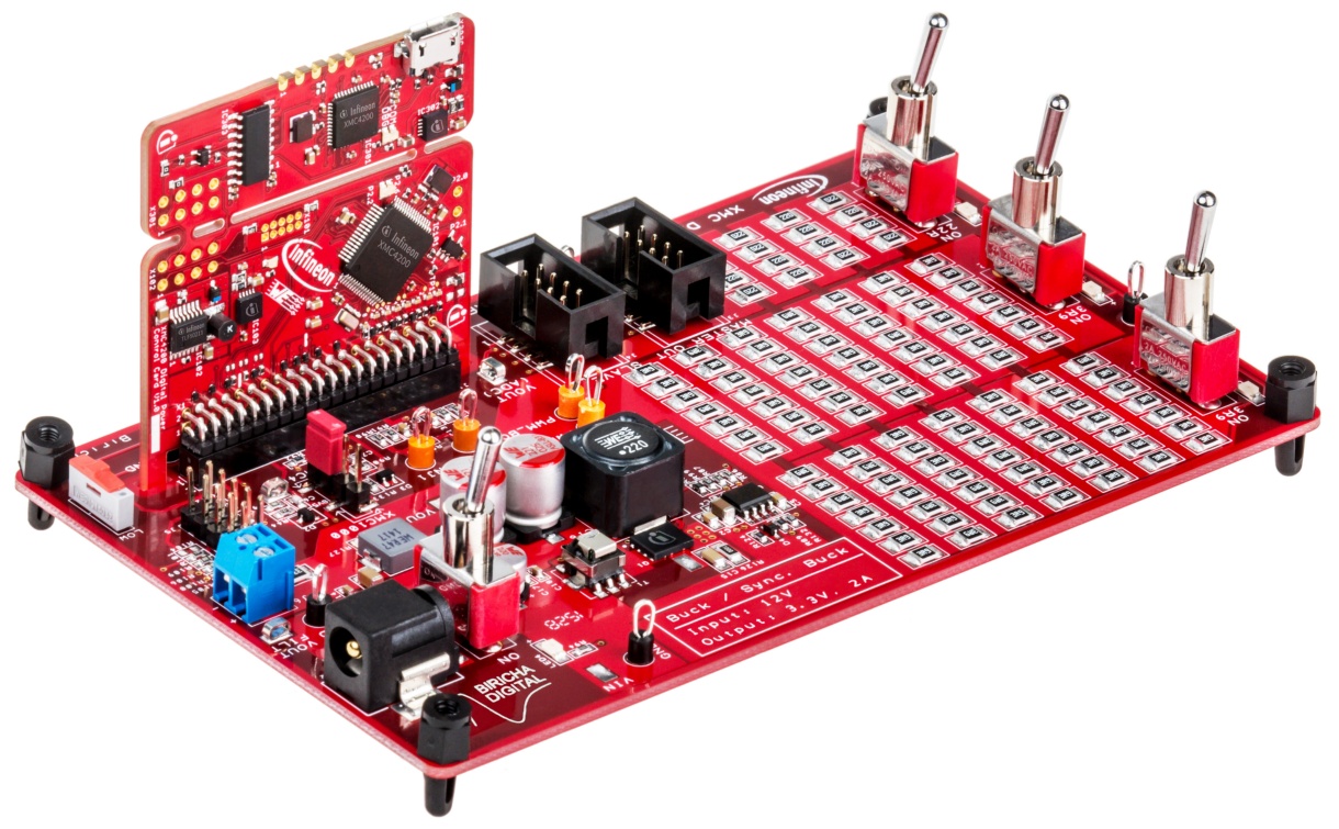
This board is designed to be used with the XMC Digital Power Explorer Kit. The kit’s power board features synchronous buck converter with on-board resistive load banks. The load banks can be switched between 10%, 55% and 100% of the maximum load, so that the transient response and the quality of the control loop under different load conditions can be tested (for example continuous conduction mode vs. discontinuous conduction mode).
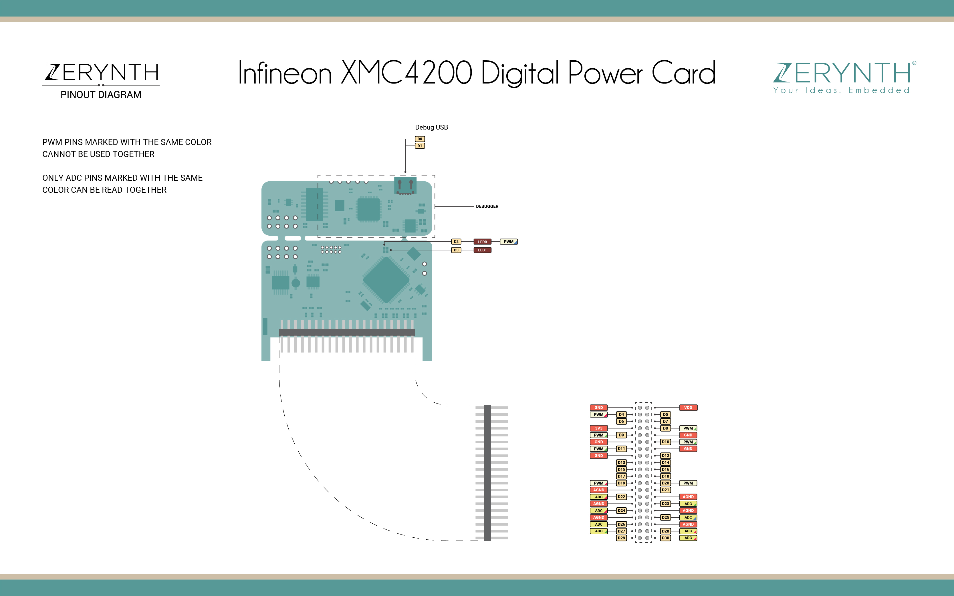
Pin Mapping
Flash Layout
The internal flash of the XMC4200 module is organized in a single flash area with 9 sectors. The flash starts at address 0xC000000.
| Start address | Size | Content |
|---|---|---|
| 0xC000000 | 16Kb | Zerynth VM |
| 0xC004000 | 16Kb | Zerynth VM |
| 0xC008000 | 16Kb | Zerynth VM |
| 0xC00C000 | 16Kb | Zerynth VM |
| 0xC010000 | 16Kb | Zerynth VM |
| 0xC014000 | 16Kb | Zerynth VM |
| 0xC018000 | 16Kb | Zerynth VM |
| 0xC01C000 | 16Kb | Zerynth VM |
| 0xC020000 | 128Kb | Bytecode Bank 0 |
Note
If flash memory must be used in a Zerynth program, it is recommended to begin using it from secure addresses towards the end the bytecode (start address of the bytecode can be found in the log console of Zerynth Studio during the uplink operation), leaving a minimum safe place to minimize the chance of clashes.
Device Summary
- XMC4200 Microcontroller based on ARM® Cortex®-M4F, 256kB Flash
- On-Board Debugger
- Connection to power board like Digital Power Explorer, via the power board connectors
- Power over USB
- 2 x user LED
Power
The XMC4200 Digital Power Control Cardboard is designed with two galvanically isolated supply domains. On the left side, there is the debug domainor isolated domain, which contains a XMC4200 MCU as on-board debug controller (OBD). The isolateddomain ispowered via the USB plug (5V) The rest of the control card is calledpower GND supply domain. This part is supplied from the power board connector and the control card will step down the input voltage to the 3.3V that XMC4200requires.This supply domain is usually powered from the power board connector. The typicalcurrent drawn bythe drive card at the power GND domain is about 65mAat 12 V input voltage.
Connect, Register, Virtualize and Program
The Infineon XMC4200 comes with a usb debugger chip on board that allows programming and opening the UART of the module. Drivers might be needed (Linux, Mac or Windows) and can be downloaded from the official JLink software page.
Note
For Linux Platform: to allow the access to serial ports the user needs read/write access to the serial device file. Adding the user to the group, that owns this file, gives the required read/write access: Ubuntu distribution –> dialout group; Arch Linux distribution –> uucp group
Once connected on a USB port, if drivers have been correctly installed, the XMC4200 device is recognized by Zerynth Studio. The next steps are:
- Select the XMC4200 on the Device Management Toolbar (disambiguate if necessary);
- Register the device by clicking the “Z” button from the Zerynth Studio;
- Create a Virtual Machine for the device by clicking the “Z” button for the second time;
- Virtualize the device by clicking the “Z” button for the third time.
Note
No user intervention on the device is required for registration and virtualization process
After virtualization, the DevKitC is ready to be programmed and the Zerynth scripts uploaded. Just Select the virtualized device from the “Device Management Toolbar” and click the dedicated “upload” button of Zerynth Studio.
Note
No user intervention on the device is required for the uplink process.